3. Implementation
This chapter will first introduce the problem of nondeterministic behavior in ROS using minimal examples in Problem Description, Sources of Nondeterministic Callback Sequences. Then, in Design Goals, the design goals and intended use cases for the implemented software are determined. Lastly, Controlling Callback Invocations to Launch System describe the implementation in detail, covering the control of callback invocations, ordering of callbacks using dependency graphs, node and system configuration files, as well as details concerning dynamic reconfiguration.
3.1. Problem Description
An important property of all testing and evaluation approaches outlined in Software Testing is determinism. A nondeterministic simulation for example may result in substantially different scenarios leading to changing evaluation metrics over multiple test runs. If the software under test itself is not deterministic, a regression test might fail even if no functional changes to the software have been made.
It can be observed, however, that even with deterministic data sources such as simulators and recordings, and deterministic algorithms under test, resulting metrics in ROS systems may be nondeterministic. This is due to nondeterministic callback execution: Varying processing times of intermediate modules and nondeterministic behavior and latencies within the communication middleware can change the order in which callbacks are executed, which may alter a node’s behavior, even if the content of the individual input messages is consistent.
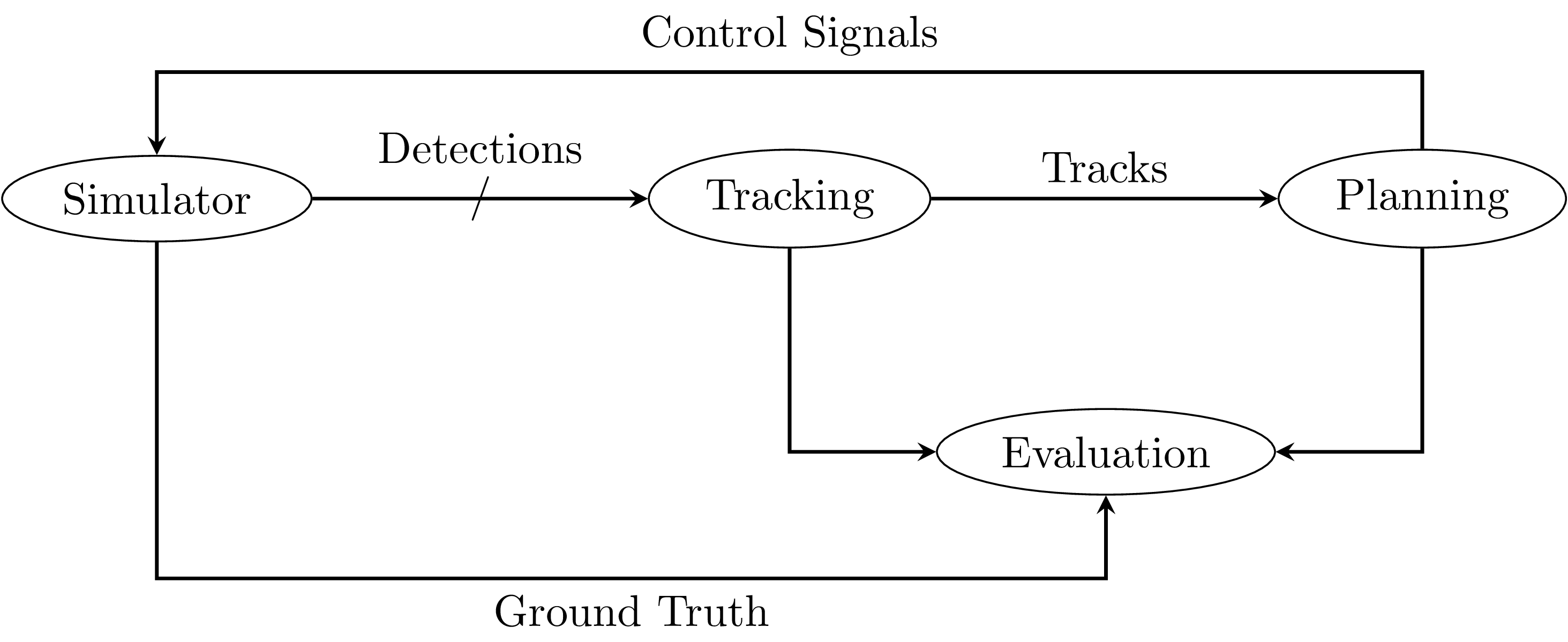
Fig. 3.1 An exemplary ROS node graph of an autonomous-driving test setup.
Fig. 3.1 displays an example ROS node graph for a testing setup in an autonomous-driving context. A simulator produces noisy object detections, which are published on multiple topics. The tracking module receives those detections and sends a combined list of tracked objects to the planning module, which generates a vehicle trajectory and appropriate control signals. Those are fed back to the simulator, updating the vehicle state. The evaluation module receives ground-truth data from the simulator and the results of the tracking and planning modules. It calculates metrics for evaluating the performance or safety of planned vehicle trajectories. The individual nodes are all assumed to be input/output deterministic, meaning that when repeating the exact same sequence of inputs, the same sequence of outputs is produced. Nondeterministic behavior of the entire system may however occur in multiple situations, which all influence the order of callbacks at each node:
The control feedback from the planning module to the simulator has variable delay, and may happen during an earlier or later simulation timestep.
The order of received detections at the tracking module is nondeterministic, which may influence its result.
If the planning module is triggered by a timer instead of by data input, it may happen before or after an input is received from the tracking module.
Those aspects may additionally be influenced by external factors such as system load and scheduling or choice of middleware implementation, leading to different evaluation results for each run.
While the system may be expected to be resilient toward such arguably small deviations in runtime behavior, such that those do not significantly degrade system performance, eliminating those is still desirable. If the system is fully deterministic with respect to callback execution, any change in performance can be unambiguously attributed to the changes made to algorithms and parameters, and performance evaluation is perfectly repeatable. Additionally, regression testing for non-functional changes would be possible by demanding exact equality of system output in response to simulated or recorded inputs.
3.2. Sources of Nondeterministic Callback Sequences
In this section, minimal examples of nodes and connecting topics will be presented, which introduce nondeterministic behavior even for deterministic nodes.
3.2.1. Lost or Reordered Messages
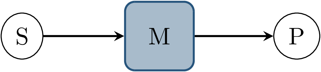
Fig. 3.2 Node graph showing a data source \(S\) and processing node \(P\), connected with topic \(M\).
Fig. 3.2 shows two ROS nodes communicating via one topic, without any additional publishers or subscribers connected to the topic.
In this scenario, the sending node publishes messages at a high rate, while the receiving node processes messages slower than required to handle every message.
This causes the subscriber queue to fill up, eventually dropping messages.
Current ROS defaults use the keep last N queue handling strategy, which would cause the oldest message to get dropped from the queue when a new one arrives.
Under varying system load, the number of processed messages changes, which leads to nondeterministic node behavior.
It should be noted that this can not be avoided by using the reliable QoS setting in ROS.
A reliably delivered message may still cause another message to be dropped from the subscriber’s queue if there is no space for the incoming message.
Messages actually getting lost during delivery, which may happen using the best-effort QoS setting on a constrained transport medium, such as a low-bandwidth wireless network, are not handled here.
A possible measure against this behavior is the keep all queuing mode, but this is often not feasible, since this may cause the queue size as well as the input-output latency of the node to grow without bounds.
Finally, message reordering might be of concern.
The DDS standard allows ordering incoming data in the BY_RECEPTION_TIMESTAMP mode, which implies that the receive order might not match the order in which the messages were
published.
While ROS does not make any claims regarding message ordering, it is assumed that the reliable QoS setting eliminates message reordering.
Nonetheless, message reordering, should it occur, is later also addressed by the same mechanism as possible queue overflow.
3.2.2. Inputs From Parallel Processing Chains
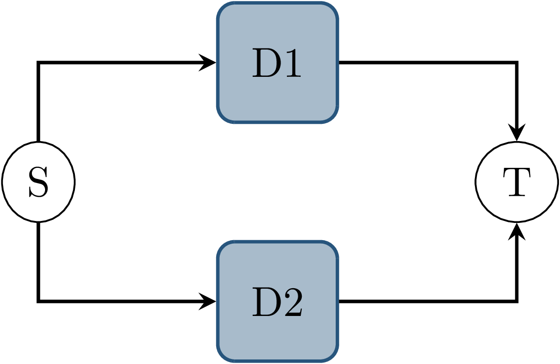
Fig. 3.3 Node graph showing a data source \(S\) and node \(T\) connected by two parallel topics \(D1\) and \(D2\), on which messages are published simultaneously by \(S\).
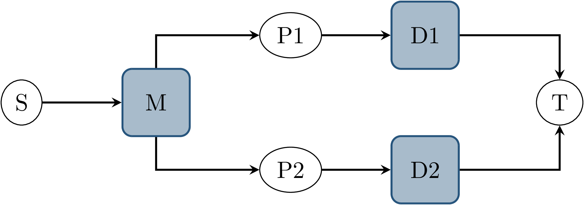
Fig. 3.4 Node graph showing data source \(S\) and node \(T\) connected by two parallel paths. Each path contains a processing node with a dedicated output topic. Both paths share the same input topic \(M\).
In this scenario, a node receives messages on multiple topics, which originate from the same event in no specified order. In Fig. 3.3, node \(S\) publishes a message to both topics \(D1\) and \(D2\) during the same callback. Usually, those messages would be regarded as published at the same time. This results in a nondeterministic receive order of both messages at node \(T\), since transmission latency might differ.
In Fig. 3.4, a similar scenario is shown. Node \(T\) again has two input topics \(D1\) and \(D2\), and a message on both topics is triggered by a single callback at node \(S\). Compared to the previous example however, \(S\) publishes a single message on topic \(M\), that is then processed by both nodes \(P1\) and \(P2\), which then produce the outputs on \(D1\) and \(D2\). This exhibits the same problem of nondeterministic receive order of both messages at node \(T\), and does so even if some assumptions about \(S\) and the transmission latency can be made. First, the nodes \(P1\) and \(P2\) add a nondeterministic processing latency to the total latency between \(S\) and \(T\). This results in nondeterministic latency, even if the transmission latency of the ROS topic was constant. Second, the data source \(S\) publishes only a single message. In the previous example, deterministic behavior might be achieved if the middleware were to guarantee immediate and synchronous delivery of messages, and if the publish order within \(S\) was deterministic. Although these assumptions are not made about the ROS middleware, and generally do not hold, this demonstrates that the problem persists even with stronger guarantees from the middleware.
3.2.3. Multiple Publishers on the Same Topic
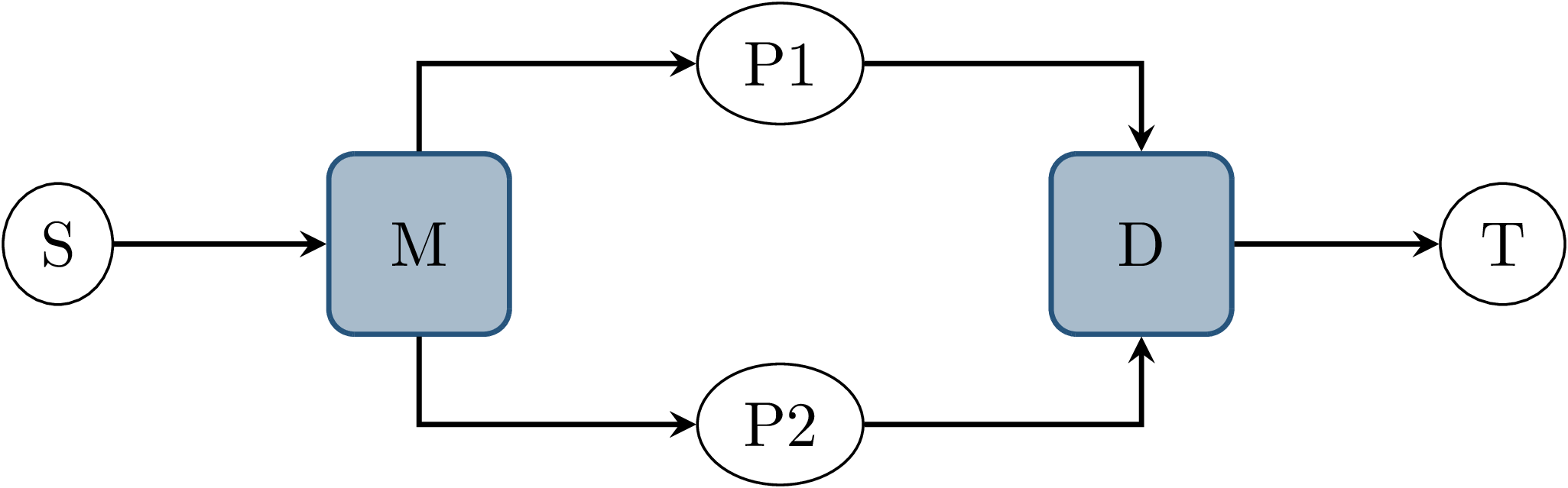
Fig. 3.5 Node graph showing data source \(S\) and node \(T\) connected by two parallel paths, where the processing nodes on both paths use the same output topic \(D\). Both paths also share the same input topic \(M\).
This scenario again consists of a data source \(S\), two processing nodes \(P1\) and \(P2\) and a node \(T\) which receives the outputs of \(P1\) and \(P2\), as shown in Fig. 3.5. Once \(S\) publishes a message, both processing callbacks at \(P1\) and \(P2\) run concurrently, eventually publishing an output. Distinct from the previous example, \(P1\) and \(P2\) use the same output topic \(D\), which consequently is the only input of \(T\). The communication middleware does not guarantee that the message delivery order at \(T\) matches the publish order at \(P1\) and \(P2\). This results in a nondeterministic arrival order of both messages at \(T\). Note that while \(P1\) and \(P2\) run concurrently in this example, this would still be a concern if the processing nodes were triggered by separate inputs since callback duration and transmission latency would still be nondeterministic.
As with the scenario in Lost or Reordered Messages, subscriber queue overflow is an additional concern here. If the subscriber queue of \(T\) is full already, a message from either publishing node may be dropped.
3.2.4. Parallel Service Calls
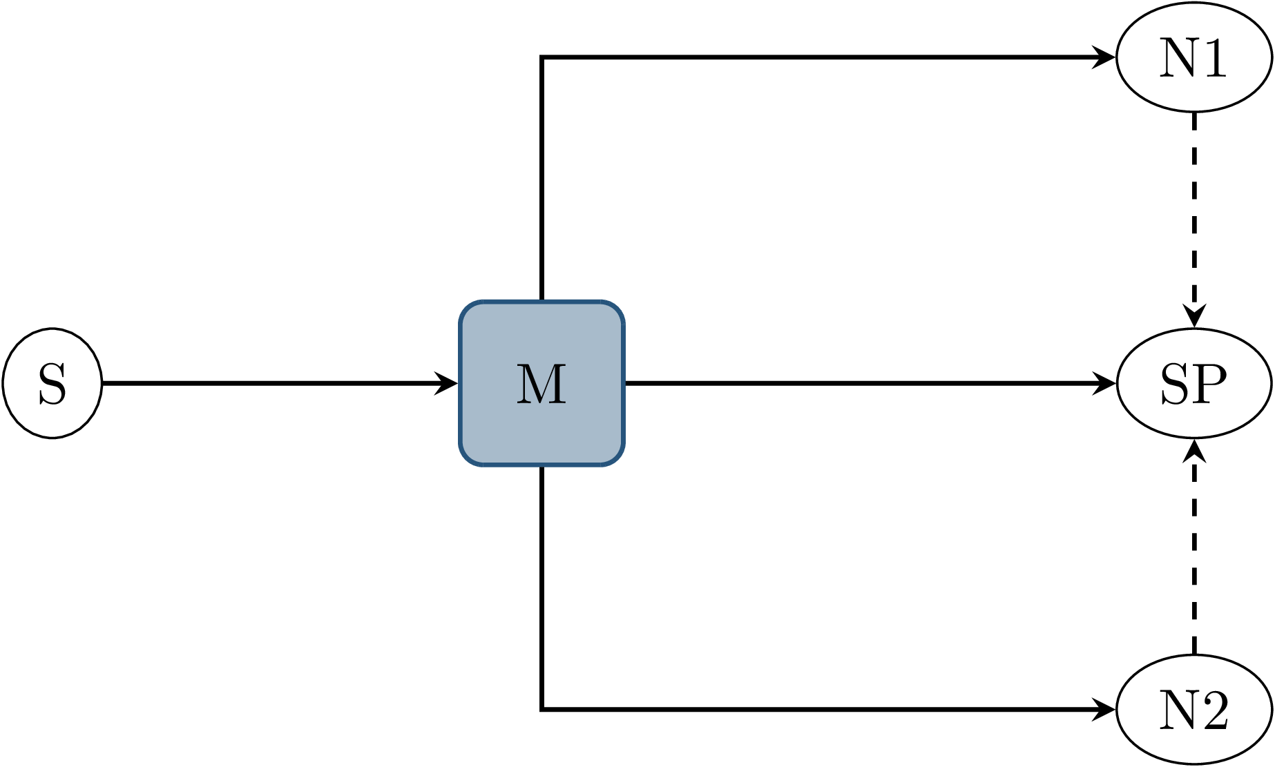
Fig. 3.6 Node graph showing three nodes \(N1\), \(N2\) and \(SP\) all with topic \(M\) as an input. Nodes \(N1\) and \(N2\) call a service provided by \(SP\) during callback execution, as indicated by the dashed arrows.
This example involves four nodes, as shown in Fig. 3.6: One node \(S\) publishes a message to topic \(M\), which causes subscription callbacks at nodes \(N1\), \(N2\) and \(SP\). \(SP\) provides a ROS service, which the nodes \(N1\) and \(N2\) call while executing the input callback. This causes three callbacks in total at the service provider node, the order of which is nondeterministic. In this case, this influences not only the future behavior of the service provider node but also the result of the callbacks at nodes \(N1\) and \(N2\), since each service response might depend on previous service calls and message inputs.
3.3. Design Goals
The goal of this thesis is to provide a framework for the repeatable execution of ROS systems, circumventing the nondeterminism caused by the communication middleware and varying callback execution duration.
In particular, the framework shall ensure that the sequence of callbacks executed at each node is deterministic and repeatable, even with nondeterministic callback durations of the entire system, arbitrary transmission delay of messages, and without guarantees of message delivery order in specific topics and between topics. This leads to fully deterministic system execution, provided the input data is deterministic, the system contains no hidden state beyond each node’s state, and all ROS nodes have a deterministic input/output behavior. The component controlling callback execution in this way will in the following be referred to as the orchestrator.
The use case for this framework is that of a researcher or developer who is evaluating the entire software stack or a specific module within the stack by some application-specific metric. The researcher expects consistent results across multiple executions and expects that changes in the resulting measure only result from changes in software configuration. Using the orchestrator during live testing, such as when performing test drives of an autonomous driving system, is explicitly not intended, as the goal of ensuring deterministic callback ordering might stand in conflict with the goal of minimizing system latency during live execution.
It is anticipated that some or all nodes within the software stack under test will need to be modified in a way to make them compatible with the framework. These necessary modifications shall be kept to a minimum and should leave the node fully operational without changes in its behavior when the framework is not in use. Additionally, the ability to integrate nodes that are non-trivial to modify is desirable. This might be the case when using external ROS nodes, not only because the developer would usually be unfamiliar with that node’s source code, but also because locally building that node might be considerably more effort compared to installing a binary distribution.
An additional design goal is to allow for runtime reconfiguration of the software stack. This includes starting and stopping nodes, changing the parameters of running nodes, or changing the communication topology. The use of the framework should not prohibit runtime reconfiguration, such as by requiring a static node graph, and the reconfiguration step itself should not cause any nondeterministic behavior.
The intended use case dictates the use of both recorded data (ROS bags) and simulators as sources of input data. For recorded data, existing ROS bags shall be usable, since re-recording data is costly and large repositories of recorded data often already exist. When using a simulation, the framework should work with existing simulators, and the integration effort shall be minimized. In the following, the specific data source used is referred to as the data provider.
Finally, the execution time impact of using the orchestrator shall be minimized. Ensuring a deterministic callback order will involve inhibiting callback execution for some time, and running callbacks serially that would otherwise run in parallel. Both this induced serialization overhead, as well as the runtime of the orchestrator itself, should be sufficiently small so as to not interfere with a rapid testing and development cycle.
3.4. Controlling Callback Invocations
In all the scenarios presented above, deterministic execution can be achieved by delaying the execution of specific callbacks in such a way, that the order of callback executions at each node is fixed. Multiple methods of controlling callback invocations have been considered, which also directly influence the general architecture of the framework:
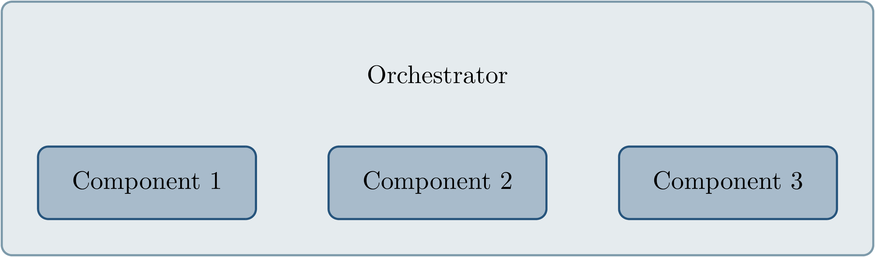
Fig. 3.7 Considered architecture of running all components within a custom execution environment, without using ROS.
The first approach is to completely avoid the ROS communications middleware and directly invoke the component’s functionality, without running the corresponding ROS callbacks. This would completely replace the ROS client library or corresponding language bindings, at least for the testing and evaluation use case, and provide a fully custom, and thus entirely controllable, execution environment. Fig. 3.7 shows the individual components contained within the orchestrator, without the ROS-specific functionality. While this approach would provide the largest amount of flexibility, and no dependency on or assumptions about ROS, this has been considered not feasible.
While some ROS nodes cleanly separate algorithm implementation and ROS communication, and allow changing the communication framework easily, this is not the case for many of the ROS nodes considered here. If a ROS node includes functionality that is tightly coupled to the ROS interface, this would require a considerable re-implementation effort. This also introduces the possibility of diverging implementations between the ROS node and the code running for evaluation, which would reduce the significance of the results obtained from evaluation and testing. Additionally, this design represents a stark difference from the ROS design philosophy of independent and loosely coupled components.
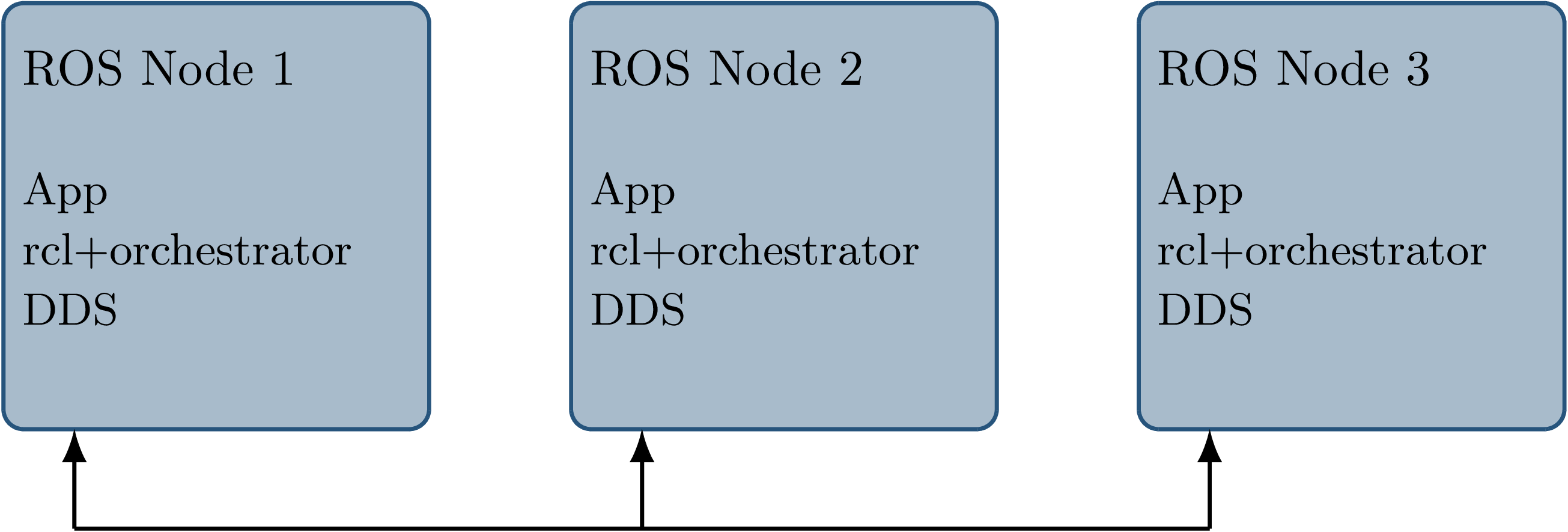
Fig. 3.8 Considered architecture of integrating the orchestrator directly into the ROS client library stack to control callback invocations via the executor. The arrows represent ROS topics connecting the nodes, which would not be changed or modified using this approach.
The second possible approach is to modify the ROS client library in order to control callback execution on a granular level.
Callback execution in ROS nodes is performed by the executor, and while multiple implementations exist, the most commonly used standard executor in the ROS Client Library for C++ (rclcpp) has previously been described in [Casini2019].
The executor is responsible for fetching messages from the DDS implementation and executing corresponding subscriber callbacks.
It also manages time, including external time overrides by the /clock topic, and timer execution.
On this layer between the DDS implementation and the user application, it would be possible to insert functionality to inhibit callback execution and to inform the framework of callback completion, as shown in Fig. 3.8.
Instrumenting the ROS node below the application layer is especially desirable since it would not require modification to the node’s source code.
This approach does however present other difficulties:
While there is a method to introspect the ROS client libraries via the ros_tracing package,
RCL does not offer a generic plugin interface or other methods to inject custom behavior.
This leaves modifying the RCL implementation, and likely also the two most popular language bindings, the ROS Client Library for Python
(rclpy) and rclcpp for C++, and building all nodes with those modified versions.
Modifying and distributing those libraries as well as keeping them up to date with the upstream versions, however, present a considerable implementation overhead.
Using custom rclpy and rclcpp versions additionally inconveniences library users, since the orchestrated version exhibits different behavior to the unmodified library, which can be unexpected and difficult to introspect.
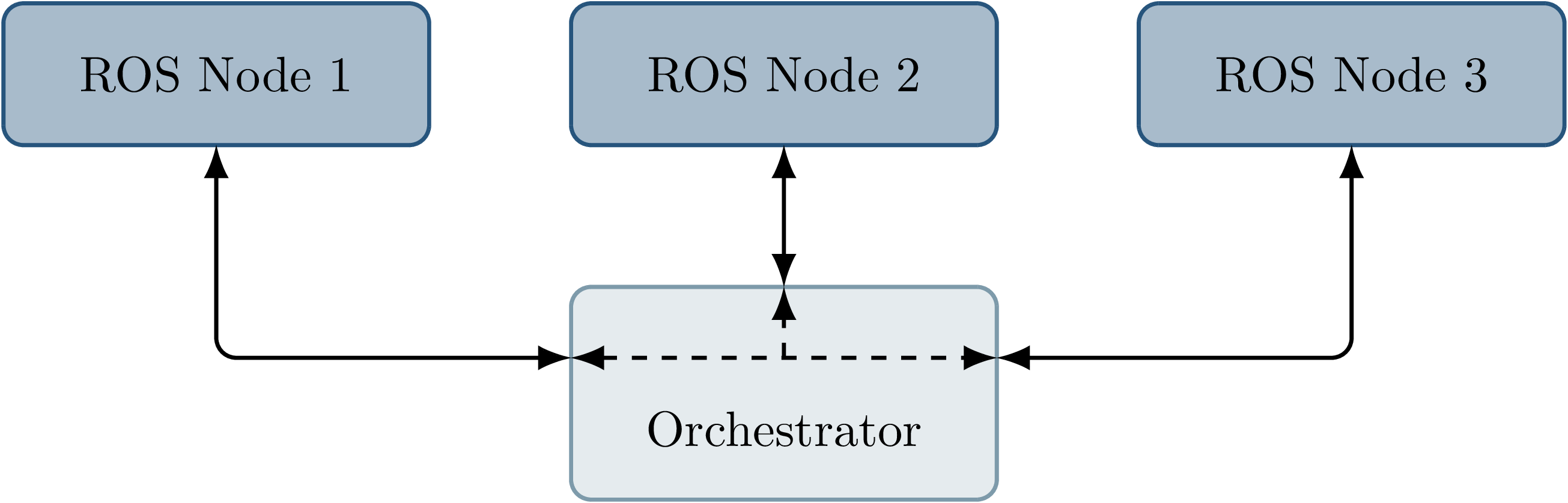
Fig. 3.9 Chosen architecture of an external orchestrator component, that intercepts all communication between nodes on a ROS topic level.
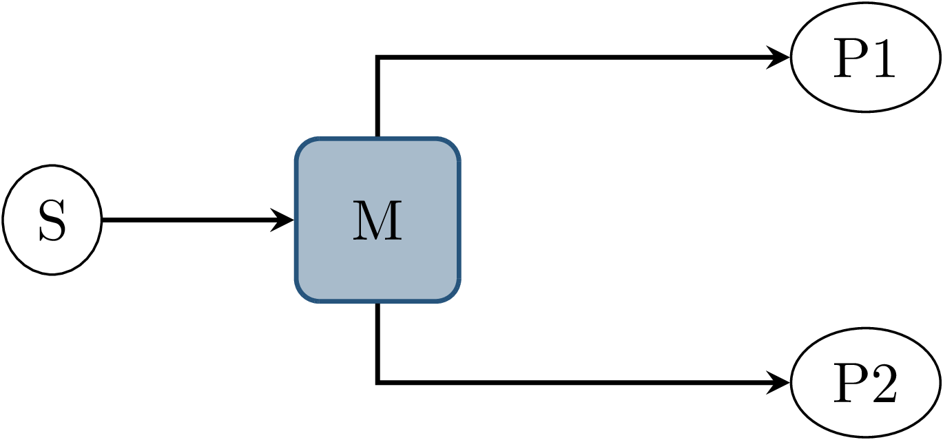
Fig. 3.10 Before interception: Data source \(S\) publishes to topic \(M\), which is an input to nodes \(P1\) and \(P2\).
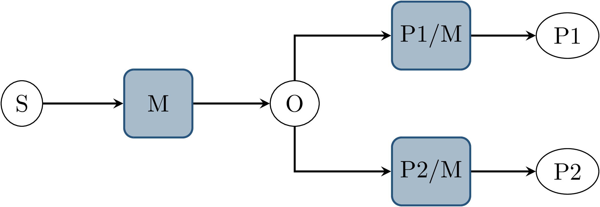
Fig. 3.11 Interception using orchestrator \(O\): The orchestrator subscribes to \(M\) and publishes to individual input topics for each node \(P1\) and \(P2\), allowing individual callback execution.
The final approach taken is to intercept the inputs to each node on the ROS-topic level: The orchestrator exists as an external component and individual ROS node and ensures that all communication passes through it, with no direct connections remaining between nodes, as visualized in Fig. 3.9. With the knowledge of the intended node inputs (which are specified in description files, as described in Node Configuration), the orchestrator can now forward messages in the same way as with the originally intended topology. Additionally, however, the orchestrator can buffer inputs to one or multiple nodes, thereby delaying the corresponding callback execution. Since the orchestrator is not expected to execute additional callbacks (which would require generating or repeating messages), delaying callbacks is sufficient to control the node’s behavior. By assigning every subscriber to a specific topic an individual connection (a distinct topic) to the orchestrator, it is also possible to separate callback executions for the same topic at different nodes. For inputs into the orchestrator, such separation is not required, since the orchestrator can ensure sequential execution of callbacks which publish a message on the corresponding topics. Fig. 3.10 and Fig. 3.11 show an example of a one-to-many connection between three nodes using one topic. When using the orchestrator, \(M\) is still used as an output of \(S\), but each receiving node now subscribes to an individual input topic P1/M and P2/M.
The orchestrator ROS node is typically located in the same process as the data provider, which would be a simulator or ROS bag player. This allows both components to interact directly via function calls, which greatly simplifies the interface compared to, for example, ROS service calls.
3.4.1. Callback Outputs
ROS callbacks may modify internal node state, but may also produce outputs on other ROS topics.
The orchestrator needs to know which outputs a callback may have, and also when a callback is done, in order to allow new events to occur at the node.
The possible outputs are configured statically, as detailed in Node Configuration.
If a node omits one of the configured outputs dynamically, or if a node does not usually have any outputs which are visible to the orchestrator, a status message must be published, the definition of which is available in Listing 3.1.
The omitted_outputs field optionally names one or multiple topics on which an output would usually be expected during this callback, but which are not published during this specific callback invocation.
1string node_name
2string[] omitted_outputs
3.4.2. Timer Callbacks
Intercepting topic inputs also allows controlling timer callback invocations, although some limitations apply.
Both in simulation and during ROS bag replay, node time is usually already controlled by a topic input through the /clock topic.
This allows the node to run as expected during slower than real-time simulation and playback.
Since the clock messages only contain the current time (and not information such as the playback rate), and ROS does not extrapolate this time, this forms a topic input that triggers timer callbacks.
Like any other topic input, this topic name can be remapped to form a specific clock topic for each node, allowing triggering timer callbacks at each node individually.
This approach is limited, however, when multiple timers exist at the same node:
Even if the timers are configured to different frequencies, the timer invocations will inevitably occur at the same time at some point.
In that instant, the /clock input triggers both (all) timers, without the ability to specifically target the callback of an individual timer.
With two callbacks running simultaneously (and depending on the executor, possibly in parallel), nondeterministic message ordering may occur if, for example, both timer callbacks publish a message to the same topic.
Thus, using multiple timers at the same node is only acceptable if the corresponding outputs are
separate.
Additionally, simultaneous execution must not change the internal node state nondeterministically, which may be ensured by using a single-threaded executor that executes the timer callbacks sequentially in a consistent order.
Using only one timer per node eliminates this problem as well, although there remains one instance where multiple timers fire at once: When each node receives the first clock input, the internal clock jumps from zero to the initial simulation or recorded time. This results in the execution of at most one “missed” timer callback, and, if the clock input is a multiple of the timer period, one “current” timer callback. The latter case is immediately observed with a simulation timer starting at a large multiple of one second, and timers running at a fraction of one second. This is an especially challenging situation since both callback invocations correspond to the same timer, compared to separate timers above. This implies that both callbacks have exactly the same outputs, making it impossible for the orchestrator to differentiate the outputs of both callback executions. A desirable property of a ROS node may be that the node itself only sets up timers when the node-local time has been initialized, which may be possible using ROS 2 “lifecycle nodes”, which have the notion of an initialization phase at node startup. In this work, however, it was considered acceptable to discard the outputs of initial timer invocations in that case, since nodes can not usually be expected to perform such initialization.
3.4.3. Callbacks for Time-Synchronized Topics
The message_filters package is not part of the ROS client library, but its popularity and interaction with message callback execution make it a relevant component to consider:
This package provides convenient utilities for handling the use case in which messages on two or more subscriptions are expected to arrive (approximately) at the same time and need to be processed together.
Specifically, it provides the ApproximateTimeSynchronizer class which wraps multiple subscribers and calls a single callback with all messages, as soon as messages have arrived on all topics within a sufficiently small time window.
While this makes the node robust against variations in message reception time and order, it complicates reasoning about the node’s behavior from the outside. The time synchronizer introduces an additional state to the node in the form of cached messages, which then influences whether a callback is executed or not for subsequent incoming messages. Additionally, the callback behavior is now dependent on the message contents, since by default the messages are not synchronized by reception time but by timestamp embedded inside the message (which might for example be the acquisition time of contained measurement data).
For handling such callbacks using the orchestrator, the following approach has been taken:
For each input of the time synchronizer, it is initially assumed that the combined callback will be invoked.
An instance of ApproximateTimeSynchronizer is additionally held at the orchestrator, which is then used to determine if the callback is expected to execute or not for a particular input message.
Since the message needs to be forwarded even when no callback is expected, a pathological error case emerges.
Consider the case in which a ApproximateTimeSynchronizer is used to synchronize messages on topics A and B, where A is published at a significantly higher rate than B.
The synchronizer may be parameterized in a way such that a message on B might be correctly combined with any of the last few messages on A.
This could lead to a scenario where many messages are published on A, without receiving any confirmation, before publishing a message on B, which causes the combined callback.
The message B might be combined nondeterministically with any message A, since for example, the latest message on A might not even be received by the node yet.
3.5. Ensuring Sequence Determinism Using Callback Graphs
Once the orchestrator has the ability to individually control callbacks at ROS nodes, it can ensure a deterministic order of callback execution at each node, leading to deterministic system execution. In order to avoid the sources of nondeterminism presented in Sources of Nondeterministic Callback Sequences, the orchestrator constantly maintains a graph of all callbacks which are able to execute in the near future. By introducing ordering constraints between callbacks as edges in the graph, and only executing callbacks when those constraints are met, the possibly nondeterministic situations presented above are sufficiently serialized to guarantee a deterministic callback order. In the following, the elements of the callback graph are discussed in detail:
A callback graph contains nodes for events that occur in the ROS system, the data provider, and the orchestrator itself.
Callback graph nodes, which each represent a callback invocation, will be referred to as actions in the following, in order to clearly distinguish them from ROS nodes, which represent individual software components (that might execute actions at specific points in time).
The orchestrator contains one callback graph, which gets extended every time the next data input is requested.
A data input is any ROS message that is not published by a node within the system under test, but originates from an external source, such as data generated by a simulator or messages from a ROS bag.
Completed actions are removed from the graph.
Edges between actions represent dependencies in execution order:
An edge \((u, v)\) from action \(u\) to action \(v\) implies that the action \(u\) must be executed after the action \(v\) has run to completion.
All outgoing edges from an action are created with the action itself.
Additional edges are not added at a later time, and edges are only removed once one of the connected actions is removed.
It should be noted that time inputs on the /clock topic for triggering timer callbacks as described in Timer Callbacks are not represented as actions, as they do not contain any message data that needs to be buffered.
Instead, the appropriate timer callback actions are created as soon as the clock input is offered by the data provider.
Once the actions are ready to execute, a corresponding clock message is sent to the node to trigger the callback.
There are four distinct types of edges:
CAUSALITY edges exist between actions that have an intrinsic data dependency, which for ROS means one action is triggered by an incoming ROS message, which the other action publishes.
The ordering of two actions connected by such an edge is guaranteed implicitly since one action is directly triggered by the other.
This means the orchestrator does not have to explicitly serialize those callbacks.
SAME_NODE edges are inserted between actions that occur at the same ROS node.
This guarantees that multiple actions at the same node, such as the callbacks for multiple different subscriptions, occur in the same order for every data input.
SAME_TOPIC edges are inserted from an action that publishes a specific topic, to existing actions that are triggered by messages on that topic.
This dependency prevents message reordering and subscriber queue overflow, by ensuring that actions that publish on a topic only run after all the actions which are triggered by a previous message on that topic.
SERVICE_GROUP edges ensure deterministic execution involving service calls.
The result of a service call is considered to be dependent on the state of the service-providing node, and all service calls are assumed to possibly alter that state.
Similarly, all other actions occurring directly at the service-providing node are also considered to alter that node’s state.
A service group for a particular service contains all actions which may call the service and all actions which occur directly at the service provider node.
The SERVICE_GROUP edge is then added to all nodes in all service groups of the services that a particular action may call.
This ensures a deterministic execution order of all actions which can modify the service-providers state.
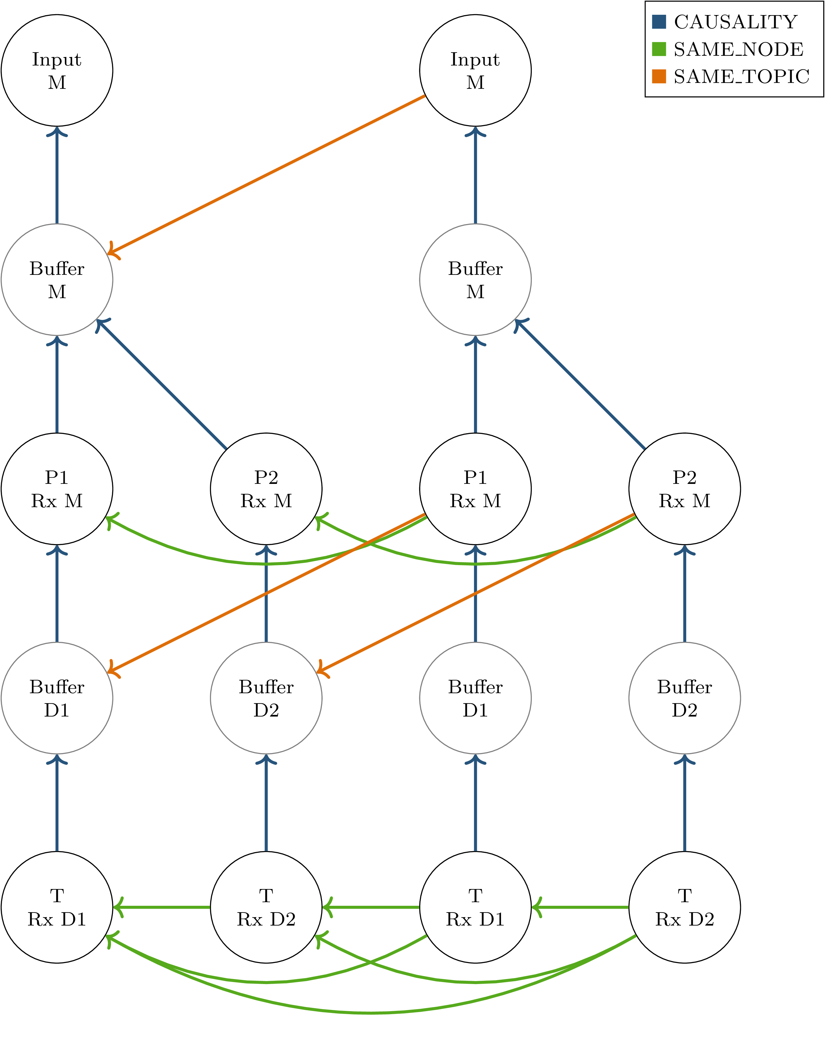
Fig. 3.12 Callback graph for two inputs into a ROS graph with two parallel processing paths as shown in Fig. 3.4.
“Input” actions represent the publishing of a topic by the data source.
“Buffer” actions represent the input of an intercepted topic at the orchestrator, potentially for forwarding to downstream nodes.
Message callbacks at ROS nodes are represented as “<node name> Rx <topic>”.
To illustrate the effects of specific edge types, the scenario from Fig. 3.4 is considered for two subsequent inputs.
The resulting callback graph is shown in Fig. 3.12.
Actions corresponding to the first input are shown in the left half of the graph.
CAUSALITY connections drawn in blue show connections directly corresponding to the ROS node graph:
They connect each callback to the previous callback publishing the required input data.
SAME_NODE edges connect the corresponding callbacks between timesteps, and the two callbacks of node \(T\) within each timestep.
This ensures that the callback order at \(T\) is deterministic even if the processing times of \(P1\) and \(P2\) are variable.
The SAME_TOPIC edges in this example might seem redundant to the SAME_NODE connections, the outgoing edge from the second data input, however, is required to ensure that both inputs are not reordered before they arrive at the orchestrator.
This graph also shows additional nodes which do not directly correspond to callbacks within the software stack under test:
The input nodes represent data inputs that may come from a ROS bag or the simulator.
Buffer nodes represent the action of storing a message at the orchestrator, and allow parallel execution by allowing SAME_TOPIC dependencies to be made to specific outputs of callbacks instead of entire callbacks.
Some elements have been excluded from this graph for brevity:
The callbacks at node \(T\) do not have any output, which requires them to publish a status message.
The reception of this status message is usually represented in the graph analogous to the buffer nodes.
3.6. Node and System Description
In order to build the callback graph, information about the node behavior and system configuration has to be available to the orchestrator. While some aspects of system configuration, such as connections between nodes could be inferred during runtime by using available introspection functionality in ROS, this is not possible for node behavior. Also, since buffering of some topics is necessary, some connections between nodes need to be redirected via the orchestrator, changing the system configuration. This type of system configuration is usually made before starting the nodes and is generally not possible during runtime.
To enable the reuse of node configuration information, the configuration is split into node configuration and launch configuration. Both of those are implemented as static configuration files in JSON format and are described in detail in the following.
3.6.1. Node Configuration
Each node requires a description of its behavior, in particular, which callbacks occur at the node and what the effects of those callbacks are. A node configuration consists of a list of callbacks and a list of provided services:
1{
2  "name": "Trajectory Planning Node",
3  "callbacks": [ ],
4  "services": [ ]
5}
Each callback specifies its trigger, possible service calls made during execution, its outputs, and flags regarding closed-loop simulation and online reconfiguration (which is described in detail in Dynamic Reconfiguration):
1{
2  "trigger": { },
3  "outputs": ["Names", "of", "output", "topics"],
4  "service_calls": ["Names of services which may be called"],
5  "changes_dataprovider_state": false,
6  "may_cause_reconfiguration": false
7}
The trigger specifies a timer, an input topic, or multiple input topics in the case of a message-filter callback:
1{ "type": "timer", "period": 40000000 }
1{ "type": "topic", "name": "imu" }
1{
2  "type": "approximate_time_sync",
3  "input_topics": ["camera_info", "image"],
4  "slop": 0.1,
5  "queue_size": 4
6}
3.6.2. Launch Configuration
The launch configuration describes the entire software stack under test. More specifically, it describes specific instances of nodes and connections between them. Each node is identified by a unique name, and the type of node is specified by reference to the corresponding node configuration file. Connections between nodes are specified using name remappings, which assign a globally unique topic name to the internal names used in the node configuration. In this example, an ego-motion estimation node is instanced for the simulated “vhcl1800” vehicle, receiving the proper sensor data input and providing the “/sil_vhcl1800/ego_motion_service” service:
1"sil_vhcl1800_ego_motion_service": {
2  "config_file": ["orchestrator", "ego_motion_node_config.json"],
3  "remappings": {
4    "imu": "/sil_vhcl1800/imu",
5    "ego_motion_service": "/sil_vhcl1800/ego_motion_service"
6  }
7}
With the corresponding node configuration:
1{
2  "name": "Ego-Motion Service",
3  "callbacks": [{
4      "trigger": {"type": "topic", "name": "imu"},
5      "outputs": []
6    }],
7  "services": ["ego_motion_service"]
8}
3.7. Dynamic Reconfiguration
Dynamically reconfiguring components during runtime (see Dynamic Reconfiguration) presents a challenge to the orchestrator, as the software setup is usually specified in advance in the launch configuration file.
To support this use case in combination with the orchestrator, the following assumptions are made with respect to the reconfiguration process:
The reconfiguration process is initiated by a ROS node during the execution of a callback. It is configured beforehand which callback may cause a reconfiguration.
Reconfiguration is instant and happens between two data inputs.
In the following, the ROS node which decides when to reconfigure the system is referred to as the “reconfigurator”. To ensure deterministic execution before, during, and after reconfiguration, coordination between the reconfigurator and orchestrator is necessary: The orchestrator provides a “reconfiguration announcement” ROS service, which the reconfigurator must call if a reconfiguration is to be performed. The orchestrator then completes the processing of all in-progress and waiting callbacks, without requesting the next data- or time input from the data provider. Once all callbacks are complete, the orchestrator then calls the reconfigurator to execute the reconfiguration. Once complete, the reconfigurator returns the new system configuration to the orchestrator. This process is illustrated in Fig. 3.13.
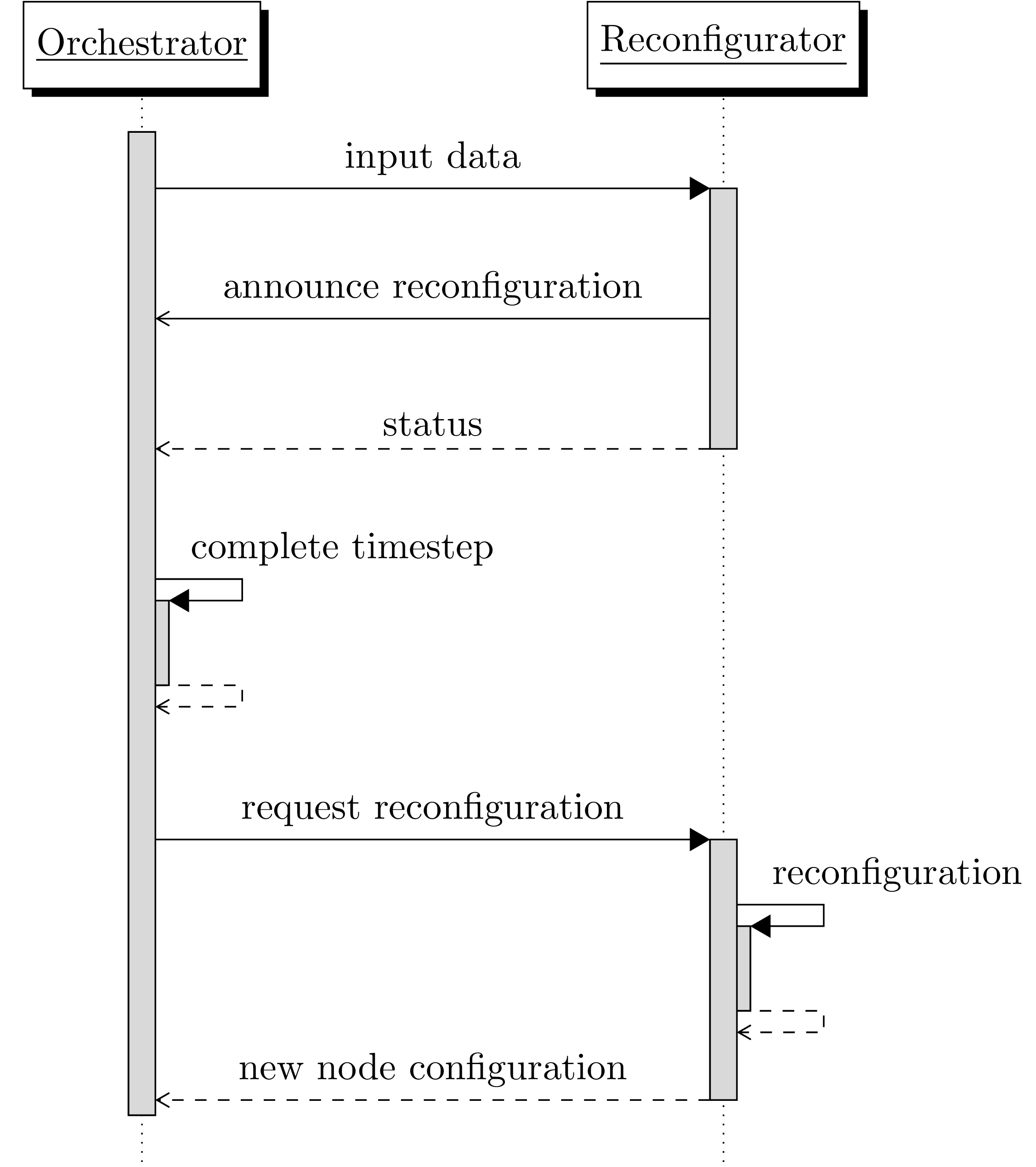
Fig. 3.13 Communication between orchestrator and reconfigurator during the dynamic reconfiguration step.
The first callback at the reconfigurator is a message callback with the may_cause_reconfiguration flag set.
The second callback is the execution of the reconfiguration service call.
After loading the new configuration, the orchestrator needs to restart execution. The ROS communication topology might however change significantly during reconfiguration. To ensure that all topics from every node are intercepted and subscribed by the orchestrator, it performs the same initialization as on startup.
At the time of writing, some restrictions exist on the type of reconfiguration actions that may be performed. In particular, creating or changing timers at an existing node, and starting new nodes containing timers is not supported. This is not inherently impossible and would be recommended as a useful extension for dynamic reconfiguration support. Implementation of this feature was omitted however due to the lack of an immediate requirement combined with the high implementation effort due to the implicit nature of triggering timer callbacks by clock inputs and the timer behavior when receiving the first clock input.
3.8. Launch System
The ROS 2 launch system is utilized to perform the initial topic interception via the orchestrator by remapping the corresponding topic names.
The orchestrator provides the functionality to automatically generate the list of required remappings from the launch and node configuration files.
These remappings map directly from the node-internal name to the intercepted topic name of the format /intercepted/{node_name}/sub/{topic_name}.
By using node-specific remapping rules of the form nodename:from:=to, all remappings can be generated in the same place and then be applied at once, which allows wrapping an existing launch file without making any modifications to it.
The following shows an example launch file that starts the software stack under test by first generating the required remappings in line 3 and then including the original launch file below.
 1def generate_launch_description():
 2    return LaunchDescription([
 3        *generate_remappings_from_config_file(
 4            "orchestrator",
 5            "sil_reconfig_launch_config.json"
 6        ),
 7        IncludeLaunchDescription(
 8            PythonLaunchDescriptionSource([
 9                PathJoinSubstitution([
10                    FindPackageShare('platform_sil'),
11                    'launch/sil.py'
12                ])
13            ])
14        )
15    ])
A limitation exists with respect to the already existing launch file due to the capabilities of the node-specific remapping in ROS:
The nodename: prefix which is used to restrict the remapping rule to one specific node, does not accept namespaces in the node name.
This might necessitate changing the use of ROS namespaces to prefixes (without a forward slash separator) for node names in the existing launch files.
Note that this limitation only applies to node names, and not to topic names.